What Are the Top RF Coaxial Connector Types for Buyers?
Choosing the right Rf Coaxial Connector can determine whether a system delivers a clean signal or a frustrating measurement.
Buyers compare more than connector shape. They must examine frequency range, impedance, insertion loss, return loss, durability, mounting style, and environmental sealing. A small SMA connector may suit laboratory equipment and compact wireless modules. A larger Type N connector may perform better outdoors, where vibration, moisture, and repeated cable movement are serious concerns. BNC connectors offer quick bayonet coupling. TNC connectors provide a threaded alternative for harsher conditions.
Signal-integrity authority Dr. Howard Johnson is widely associated with the principle, “Every interconnect is a transmission line.” That idea matters here. The connector is not just a metal joining piece. Its geometry affects reflections, shielding, and signal continuity. A poorly matched connector can behave like a narrow bottleneck in an otherwise capable RF path.
Real buying decisions are rarely perfect. Catalog specifications may look impressive, yet compatibility problems can appear during installation. A 50-ohm connector should not be casually paired with a 75-ohm system. It may fit physically, but electrical performance can suffer. That mistake is easy to make.
This guide examines the top RF coaxial connector types for buyers. It compares their strengths, limitations, common applications, and selection risks. Expect practical details, including panel space, torque, cable size, and weather exposure. The best choice is not always the smallest or cheapest. It is the connector that remains reliable in the actual system.
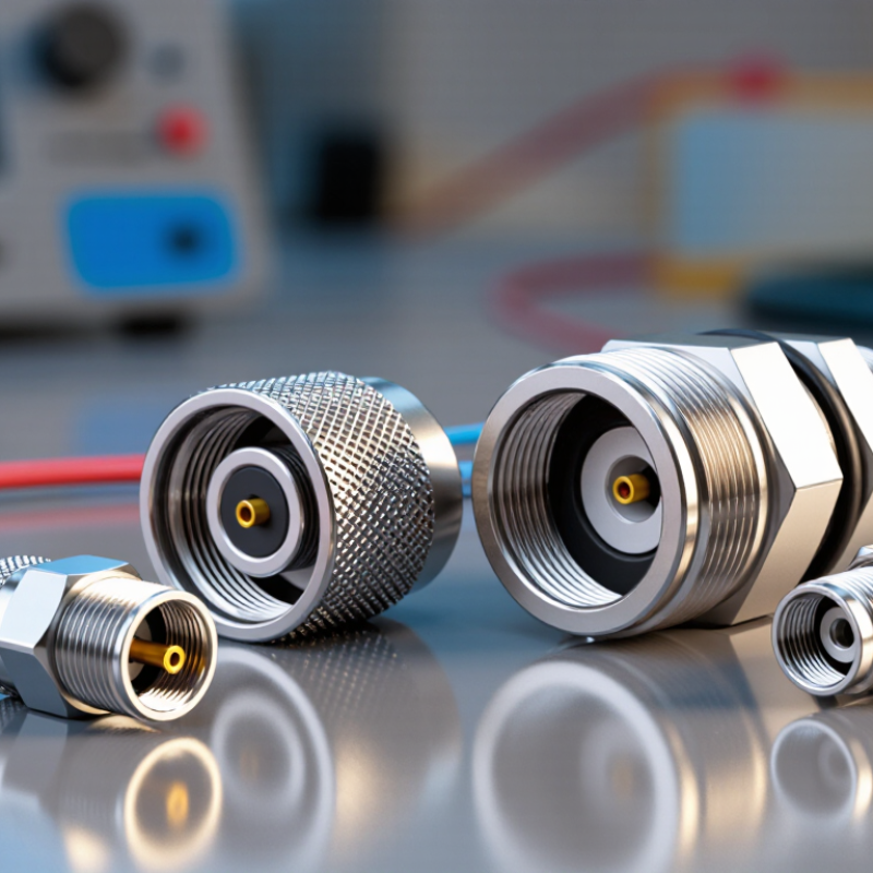
RF Coaxial Connectors: Definition, Structure, and Core Functions
RF coaxial connectors join radio-frequency cables, antennas, filters, and equipment while preserving controlled impedance. Their basic structure includes a center contact, dielectric insulator, outer conductor, and protective body. The center contact carries the signal. The outer conductor limits radiation and reduces interference. Most systems use 50-ohm impedance, while television infrastructure commonly uses 75 ohms. Small details matter. A loose interface can create reflections, insertion loss, and unstable readings.
Common buyer choices include SMA, N, BNC, TNC, SMB, MCX, and MMCX types. SMA suits compact equipment and high-frequency laboratory assemblies. N connectors offer stronger outdoor protection and better mechanical stability. BNC supports fast bayonet coupling, while TNC improves vibration resistance through threaded engagement. MarketsandMarkets’ 2024 RF connectors research identifies telecommunications, wireless infrastructure, automotive systems, and test equipment as important demand areas. Grand View Research also estimated the global RF connector market at roughly USD 3 billion in 2023, with continued expansion expected.
Selection should match frequency, impedance, power, cable size, sealing level, and mating cycles. A connector may meet its datasheet rating yet perform poorly after repeated assembly. I have found that torque control and clean contact surfaces often matter more than appearance. Do not ignore installation space. A larger connector may survive harsh conditions but obstruct a crowded panel. Reported market forecasts are useful, not absolute. Actual performance depends on cable quality, assembly skill, temperature, and measurement methods.
How RF Coaxial Connectors Are Classified by Design and Performance
What Are the Top RF Coaxial Connector Types for Buyers?
RF coaxial connectors are classified by interface design, electrical performance, and operating environment. Threaded connectors provide strong vibration resistance and stable contact pressure. Bayonet designs connect quickly, which helps during field maintenance. Snap-on and push-pull styles save time, but they may need tighter mechanical checks.
Performance classification starts with impedance, commonly 50 or 75 ohms. A mismatch can increase reflections and weaken signal quality. Frequency range also matters, especially in high-speed wireless and measurement systems. Buyers should check insertion loss, return loss, power handling, and voltage rating. Small connectors often support compact assemblies, while larger types handle higher mechanical stress and power.
Environment changes the decision. Sealed designs suit outdoor cabinets, antennas, and equipment exposed to dust or moisture. Some connectors use corrosion-resistant plating and locking features for harsh locations. In practical assembly work, cable size and bend radius are easy to overlook. I have seen a technically suitable connector fail because the cable was pulled too sharply. That was not a frequency problem. It was an installation problem. Cost can influence selection, but lifecycle reliability deserves equal attention. No single connector type fits every system, and the most familiar option is not always the safest choice.
What Are the Main Types of RF Coaxial Connectors for Buyers?
Buyers should match the RF coaxial connector type to frequency, power, environment, and installation space. SMA connectors suit compact microwave assemblies and commonly support frequencies up to 18 GHz, depending on design. N-type connectors offer stronger outdoor performance, better sealing, and lower loss for base stations or test equipment. BNC connectors use a quick bayonet lock and remain practical for instruments operating below approximately 4 GHz.
TNC connectors add a threaded coupling, improving vibration resistance over standard BNC designs. SMB and MCX connectors save space inside compact radios, navigation units, and embedded devices, but their smaller interfaces can be less robust. According to a 2024 MarketsandMarkets report, the RF connectors market is expected to grow from roughly USD 4 billion in the mid-2020s, driven by wireless infrastructure, aerospace systems, and connected equipment. That growth does not make every connector interchangeable.
Check the details.
Buyers should compare impedance, usually 50 or 75 ohms, with the cable and equipment. A mismatch can increase return loss and create visible signal reflections during testing. The IEC 61169 series provides dimensional and performance requirements for several RF connector interfaces, offering a useful verification reference. Still, field experience shows that connector quality alone cannot fix poor cable routing, excessive bending, or an incorrectly tightened coupling. A low-cost option may pass a basic continuity check yet fail after repeated mating cycles. That is where many purchasing decisions need more reflection.
What Are the Top RF Coaxial Connector Types for Buyers?
The chart compares representative upper frequency ratings for widely used RF coaxial connector types. Actual performance varies by connector design, cable assembly, impedance, and manufacturer specifications.
SMA connectors are commonly selected for compact, high-frequency applications, while N and 7/16 DIN connectors are often preferred for outdoor, cellular, and higher-power systems. BNC and TNC connectors support quick or threaded connections, and F connectors are widely used in lower-frequency broadband and video systems. Buyers should also verify impedance, environmental sealing, mating style, durability, and power requirements.
How to Compare Connector Frequency, Impedance, and Power Ratings
RF coaxial connector selection starts with three linked figures: frequency, impedance, and power. A connector rated for 6 GHz may perform poorly above that point. 3GPP TS 38.104 Release 17 defines 5G operating ranges from 410 MHz to 7.125 GHz for FR1, and 24.25 GHz to 71 GHz for FR2. Buyers should match the connector’s tested range, not its appearance.
Impedance must match the complete signal path. Most measurement and wireless systems use 50 ohms, while many video systems use 75 ohms. Mixing them can increase reflections and standing-wave ratio. IEC 61169-1 identifies key connector characteristics, including impedance, interface dimensions, and electrical performance. Match it. Do not guess.
Power ratings need closer inspection. A connector’s maximum power usually falls as frequency rises, especially with continuous-wave signals. Temperature, cable size, contact condition, and VSWR also change the safe limit. IEEE Std 287-2006 provides measurement guidance for coaxial systems, but catalog values still require context. A 100-watt rating at 1 GHz should not be treated as 100 watts at 10 GHz. That shortcut is tempting, and sometimes wrong.
For purchasing, request insertion-loss, return-loss, and power curves across the actual operating band. Verify whether the rating covers continuous power, peak power, or both. A vector network analyzer can expose a poor interface quickly. Real installations are less perfect than datasheets. Allow margin.
What Are the Top RF Coaxial Connector Types for Buyers? - How to Compare Connector Frequency, Impedance, and Power Ratings
| Connector Type | Typical Impedance | Typical Maximum Frequency | Representative CW Power at 1 GHz | Coupling Method | Relative Size | Common Use Cases | Buyer Considerations |
| N-Type | 50 Ω or 75 Ω | Approximately 11 GHz | Up to approximately 300 W | Threaded | Large | Base stations, antennas, wireless infrastructure, test equipment | Strong outdoor performance and relatively high power handling; verify the exact frequency rating and weatherproofing. |
| 7/16 DIN | 50 Ω | Approximately 7.5 GHz | Up to approximately 1,500 W | Threaded | Very large | High-power cellular, broadcast, and communication systems | Excellent power capability and low passive intermodulation potential, but it requires more installation space. |
| BNC | 50 Ω or 75 Ω | Approximately 4 GHz | Up to approximately 100 W | Bayonet | Medium | Oscilloscopes, laboratory instruments, video, and general RF equipment | Fast mating and widely available; choose the correct 50 Ω or 75 Ω version because they are not electrically interchangeable for every application. |
| TNC | 50 Ω | Approximately 11 GHz | Up to approximately 100 W | Threaded | Medium | Mobile radio, antennas, navigation equipment, and outdoor instrumentation | Provides better vibration resistance than a bayonet connector; useful where secure mating is important. |
| SMA | 50 Ω | Approximately 18 GHz | Up to approximately 50 W | Threaded | Small | RF modules, microwave instruments, antennas, and compact test assemblies | Good high-frequency performance in a compact package; power decreases as frequency rises and depends strongly on the cable assembly. |
| SMB | 50 Ω or 75 Ω | Approximately 4 GHz | Up to approximately 50 W | Snap-on | Very small | Internal equipment connections, automotive electronics, and compact RF assemblies | Quick installation and small size; less suitable for repeated vibration or high mechanical loads than threaded types. |
| SMC | 50 Ω | Approximately 10 GHz | Up to approximately 100 W | Threaded | Very small | Compact instrumentation, avionics, communications, and embedded RF equipment | Combines compact dimensions with threaded retention; confirm torque requirements and available cable options. |
| 2.92 mm | 50 Ω | Approximately 40 GHz | Up to approximately 20 W | Threaded | Ultra-small | Millimeter-wave test systems, radar, high-speed measurements, and precision modules | Suitable for broadband measurements up to 40 GHz; assembly quality, connector cleanliness, and torque control are critical. |
| 2.4 mm | 50 Ω | Approximately 50 GHz | Up to approximately 10 W | Threaded | Ultra-small | Precision microwave, radar, antenna measurement, and high-frequency test equipment | Offers higher frequency capability than 2.92 mm; it requires careful handling and compatible high-frequency components. |
| 1.85 mm | 50 Ω | Approximately 65 GHz | Up to approximately 5 W | Threaded | Ultra-small | Advanced millimeter-wave research, high-speed communications, and precision network analysis | Designed for very high frequencies; mechanical tolerances, connector wear, and calibration practices have a major effect on results. |
Note: Frequency and power figures are representative engineering values for comparison, not universal limits. Actual ratings vary with connector design, cable type, VSWR, ambient temperature, altitude, duty cycle, and mating condition. Always confirm the manufacturer’s datasheet for the exact part number and application.
Which RF Coaxial Connector Best Fits Your Application and Budget?
Choosing the right RF coaxial connector starts with the application, not the catalog price. SMA connectors suit compact equipment and frequencies commonly reaching 18 GHz. N-type connectors offer stronger outdoor protection and better power handling. BNC connectors remain practical for instruments requiring quick bayonet coupling. For dense assemblies, MCX, MMCX, or SMP options can reduce space, but their smaller bodies need careful handling.
The budget gap is often hidden in installation. A low-cost connector may require extra adapters, cable work, or replacement after repeated mating. MarketsandMarkets’ 2024 RF connector study estimates the market could grow from approximately USD 2.7 billion in 2023 to USD 3.9 billion by 2028. That growth reflects demand for reliable signal connections across wireless infrastructure, testing, and industrial electronics. It does not mean every application needs a premium connector.
Check frequency, impedance, voltage standing wave ratio, mating cycles, environmental sealing, and cable diameter. A 50-ohm connector should match a 50-ohm system. Even small mismatches can increase reflection loss. The International Electrotechnical Commission’s IEC 61169 series provides useful interface and performance references. For outdoor cabinets, an N-type connector may justify its higher cost. For a protected laboratory panel, BNC may be sufficient. I would still verify the datasheet and measure a sample assembly. Real cable routing can expose assumptions that look reasonable on paper.
